Post Tensioned Cables
The Invisible Muscle: Engineering the Weightless Slab
Construction / Post-Tensioned Concrete / Goldstein ResidenceIn modern residential architecture, we often chase the "impossible" cantilever—those thin, gravity-defying planes that define the work of John Lautner or Pierre Koenig. But to achieve that aesthetic of weightlessness, the structure has to work twice as hard. Beneath the serene underside of a cantilevered slab, an enormous amount of invisible force is being managed with extraordinary precision.
This is where Post-Tensioned (PT) Cables come in. Unlike conventional rebar, which is passive—a static grid waiting to resist stress—PT cables are an active system. We aren't simply reinforcing the concrete; we are pre-loading it with immense compression, causing it to behave like a rigid, high-strength spring in permanent tension against itself.
The Anatomy of the Deck
The process begins with a meticulous formwork layout. On this project, we used a board-form finish inlay on top of the plywood decking—a critical detail. This ensures that the underside of the finished slab retains the organic texture of wood grain once the forms are stripped, producing a ceiling with material memory rather than a featureless soffit.
 Concrete deck with electrical boxes installed
Before the first cable is run, hundreds of electrical boxes and conduits must be precisely located and set. In a PT slab, there is no margin for error—and no going back. Once those cables are stressed, drilling into the concrete is a high-stakes gamble that risks severing a tendon under tens of thousands of pounds of load.
The Installation: A Steel Network
The cables arrive in massive rolls, each strand greased inside a plastic sheath to allow for free movement during stressing. At the edges, we use encapsulated anchors to provide a watertight seal—a critical defense against the Achilles heel of PT systems: cable corrosion. A corroded tendon in a PT slab is not a maintenance issue. It is a structural emergency.
 Post-tension cable rolls on site
The installed layout resembles a complex, woven basket of steel running in two perpendicular directions across the deck. But the cables are not simply level. Because this slab varies in depth, each cable must drape in a calculated wave—rising high over the column supports, where compression is needed at the top fiber, and drooping low at mid-span, where the bottom fiber must be placed in compression. This parabolic profile is not incidental; it is precisely engineered by the structural engineer to counteract the weight of the building itself.
 Post-tensioning anchors along the edge of the form
 Post-tension cable installation in progress
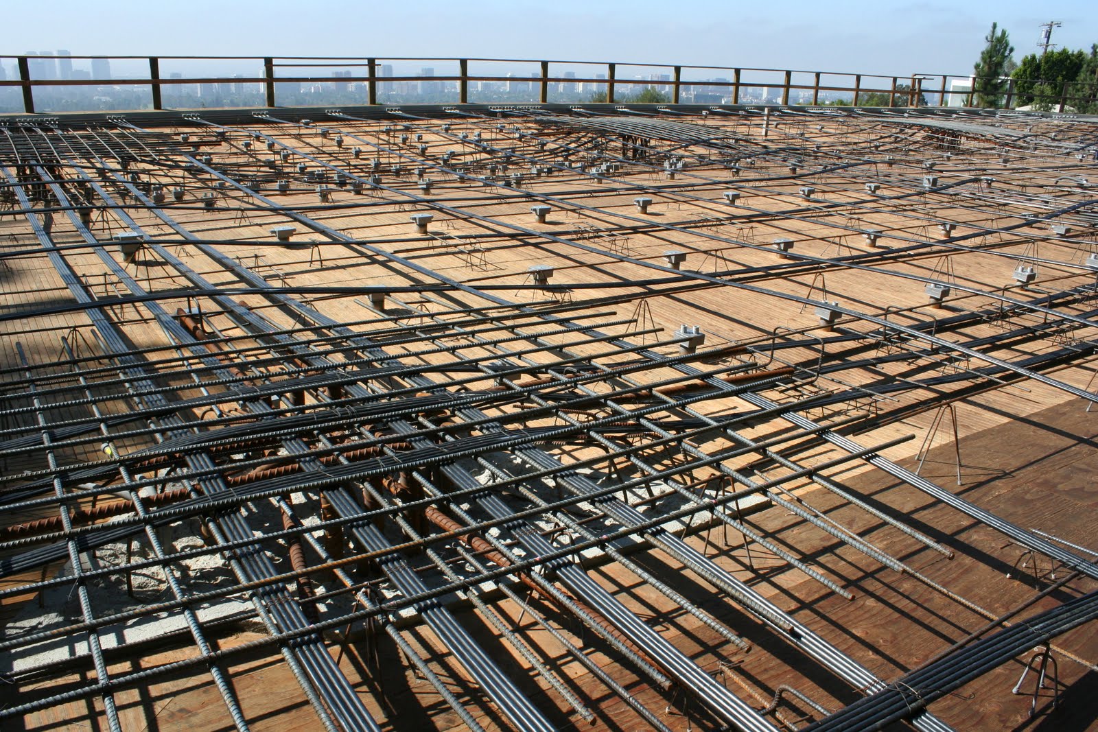 Post-tensioning layout — the calculated wave of steel
The Wedges: A Mechanical Lock
 Post-tensioning wedges — the teeth grip and lock the cable
The post-tensioning wedges are installed in pairs around the cable inside the cone openings at the slab edge. Look closely at the wedge geometry and you'll see the elegance of the mechanism: angled teeth that permit the cable to pull freely in one direction, but cinch and lock the moment the cable tries to release. As the hydraulic jack pulls the tendon and then releases, the wedge shape is driven hard against the embedded anchor. The force locks in. The excess cable is torched off flush, and the full post-tensioning load is transferred to the slab—measurably compressing and even lifting it off the forms.
 Wedges installed and seated — ready for stressing
Each cable edge is marked with spray paint prior to stressing. That mark is the inspector's reference: after the jack engages, the elongation is measured against the shop drawing specification—approximately 5 inches of pull per 60-foot cable strand. If the elongation is off, the cable is not performing as modeled, and we stop.
The Stressing: 33,000 Pounds of Force
Once the concrete cures to a specified compressive strength, the transformation begins. A hydraulic stressing jack is inserted into the anchor cone and grips the cable. The pump engages. The operator brings the system up to pressure—approximately 33,000 lbs of force per tendon—and you can actually see the slab begin to lift off the form below as the internal tension takes over from gravity.

The jack is powered by a hydraulic pump and returns to its start position after each pull. A second operator moves the unit to the next cable while the first documents the elongation reading. Cable by cable, the slab is activated—an entire structural field waking up under load.
 Inspector documenting elongation per tendon — each cable is confirmed to specification
Completion: Sealing the System
After each cable is stressed and the elongation confirmed, the excess tendon is cut close to the wedge face. A plastic encapsulating cap packed with grease is fitted over the exposed end, sealing the anchor assembly against moisture intrusion. The recessed cone pocket at the slab edge is then filled with a corrosion-inhibiting grout, and a bituminous waterproofing layer is painted over the full perimeter edge as a final line of defense.
 Cone pockets filled with corrosion-inhibiting grout — the final seal on the system
What remains, once the forms come down, is the invisible muscle: a slab in permanent, active compression, capable of spanning distances and achieving cantilevers that passive reinforcing alone could never permit. The weightlessness is not aesthetic sleight of hand. It is structural honesty—achieved through immense, hidden force.
Comments
Post a Comment